
Part of our Building Your First Ham Radio Station guide.
Wire antennas will get you a long way, but serious DX eventually pushes you toward two things: pointing your signal where you want it, and hearing weak stations through the noise. This guide covers the hardware for both, compact beams and the rotator to turn them, dedicated receive antennas and diversity receive, plus the free modeling software that lets you test a design before you buy or build anything. If you’re still deciding between antenna types for DX, start with Vertical vs Yagi vs Wire for DX.
Jump to: Hex beams and quads · Rotators · Beverage and K9AY receive antennas · Diversity receive · Modeling software
Hex Beams and Cubical Quads: Compact Gain Antennas
A full-size multiband Yagi delivers serious gain, but it also demands a serious tower and a lot of real estate. Hex beams and cubical quads exist for hams who want real directional gain without going that far. (For the Yagi itself, see What Is a Yagi Antenna.)

The hex beam’s folded wires
A hex beam strings folded wire elements between spreader arms in roughly a hexagon. The result is a compact, lightweight antenna that still produces real forward gain and front-to-back ratio on several bands from one feed point. Because the elements fold back on themselves instead of running straight out like a Yagi’s, a hex beam covers a set of bands in a dramatically smaller turning radius, which matters a lot on a small tower or with a light rotator. I own a Buddipole BuddiHex, and I wrote up how it did in my Field Day 2026 report.
The cubical quad’s closed loops
A cubical quad uses full-wave loop elements, similar in principle to delta and horizontal loops, arranged as a driven element plus reflectors and directors. It’s the same beam concept as a Yagi built from loops instead of straight elements. Quads have a reputation for slightly quieter receive and a bit more gain per element than an equivalent Yagi, though construction is more involved, with a spreader frame holding each loop’s shape.
Which one to build
Hex beams have become the more popular compact multiband beam, mostly because commercial kits make the build approachable without custom fabrication. Quads reward hams who want to build and tune their own antenna and want what loops bring. For most people who want directional gain without a full tower, a commercial hex beam kit on a modest tower or roof mount is the practical starting point.
- Wind and ice: both use fiberglass spreaders. Quads present more surface area and collect more ice in winter climates.
- Rotator: both need one to be useful. A hex beam’s small turning radius and light weight let you use a lighter rotator than a quad or Yagi.
- Height: both work best high and clear, but a hex beam on a modest push-up mast or roof tripod still gives useful gain.
- Band coverage: commercial hex beams commonly cover five or six bands from 20 through 6 meters, while quads are often built for fewer bands.
- Maintenance: wire elements can stretch or shift, so check tuning after the first season.
If you’re deciding between a hex beam and a small tribander Yagi, compare turning radius and weight first. For many backyard installs, those two numbers decide it.
Antenna Rotators: Do You Need One, and How to Choose
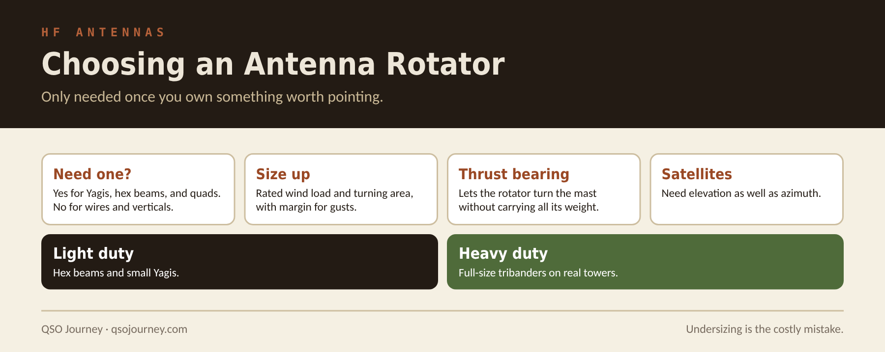
A rotator only matters once you put up a directional antenna: a Yagi, a hex beam, a quad, anything with a real front-to-back pattern worth pointing. Before that, it’s an expensive way to spin a piece of metal.
When you actually need one
With wire antennas, verticals or anything omnidirectional, a rotator does nothing for you. Add a beam, though, and being able to point it at the DX you’re chasing, instead of wherever it happened to be mounted, can be the difference between a workable contact and nothing. Rotators also help point directional VHF and UHF antennas at distant repeaters.
Sizing it correctly
Rotators are rated by turning torque and by the wind load and turning radius they can safely handle, and undersizing one is a common, expensive mistake. A rotator rated for a small VHF Yagi will burn out or fail mechanically trying to turn a full-size HF beam in real wind. Size up from the manufacturer’s stated capacity for your actual antenna, since real gusts routinely exceed the steady-state numbers behind the ratings.
For a hex beam or small Yagi on a modest tower, a light-duty rotator built for that class is usually enough and much cheaper than the heavy-duty units made for full-size tribanders. Whatever you buy, budget for a thrust bearing to take the antenna’s weight off the rotator. Rotators are built to provide turning torque, not to carry the mast and antenna indefinitely.
Installation tips
- Mount the rotator inside a tower or on a proper rotator plate, not clamped to the side of a mast where it carries the full side load.
- Leave a service loop in the coax at the rotator so the antenna can turn its full range without pulling on the cable.
- Calibrate the control box so the indicated direction matches where the antenna actually points.
- Use the recommended control cable and protect it from lightning with a proper entry panel.
- Check the mast clamp bolts after the first few storms. Slippage is the most common reason a beam points somewhere other than the display shows.
Most modern controllers can be computer controlled, so your logging software can point the antenna at a station’s bearing automatically. That’s a real convenience once you’re chasing DX regularly.
Beverage and K9AY Receive Antennas for Low-Band DX
On 80 and 160 meters, the noise floor is often the real limit on working DX, not your transmit power. A dedicated receive antenna, separate from the one you transmit on, can pull weak low-band signals out of noise your main antenna simply can’t reject.
The Beverage: brute-force directivity
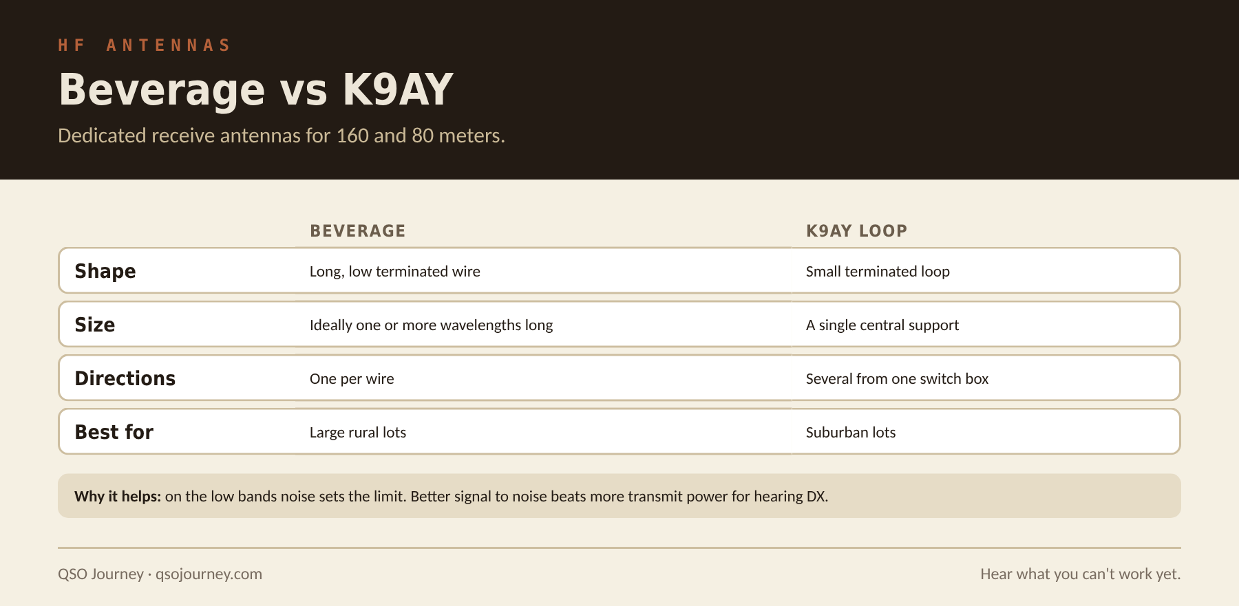
A Beverage is about as simple as antennas get: a long, low horizontal wire, ideally several wavelengths long, run close to the ground and terminated at the far end with a resistor matched to its characteristic impedance. That termination gives it a strongly one-way receive pattern, favoring signals from the direction the wire points and rejecting noise from behind. The catch is space: a proper 160 meter Beverage wants hundreds of feet in a straight line, which rules it out for most suburban lots.
The K9AY: directivity in a small footprint
The K9AY loop, developed by Gary Breed, K9AY, solves the space problem. It’s a small terminated loop, usually a diamond on one central support and only a few dozen feet across, with a truly directional receive pattern in a fraction of a Beverage’s footprint. Many K9AY designs use a switch box to select between several directions from one installation, giving you steerable low-band receive without multiple antennas.
If you’re serious about 160 and 80 meter DX and your transmit antenna is a compromise vertical with a noisy receive pattern, a dedicated receive antenna is one of the highest-value upgrades you can make. It often does more for actually hearing weak DX than a big investment in the transmit antenna. If your lot allows a K9AY, I’d start there before a Beverage.
Making a receive antenna work in your shack
- Use your radio’s separate receive antenna input if it has one, so the receive antenna is switched in only on receive. The IC-7300 Mark II has one, and I cover it in my IC-7300 Mark II shack setup.
- Protect the radio. A receive antenna near your transmit antenna can pick up enough RF to damage a receiver front end, so use a switch or protection device that disconnects or shorts it on transmit.
- Add a preamp if needed. Beverages and small loops have low output, and many stations add a preamp to lift signals above the receiver’s own noise.
- Keep the feedline quiet with chokes and good grounding, or noise riding on the coax will undo the benefit. See common-mode current.
Mount the receive antenna as far from your transmit antenna as practical. Strong coupling between the two distorts the receive pattern and erases the directivity you built it for.
Two-Radio Diversity Receive: Fighting Fading With a Second Antenna
Diversity receive is a technique borrowed from serious contest and DX stations: a second antenna and receiver running at the same time to fight fading in a way one antenna can’t.
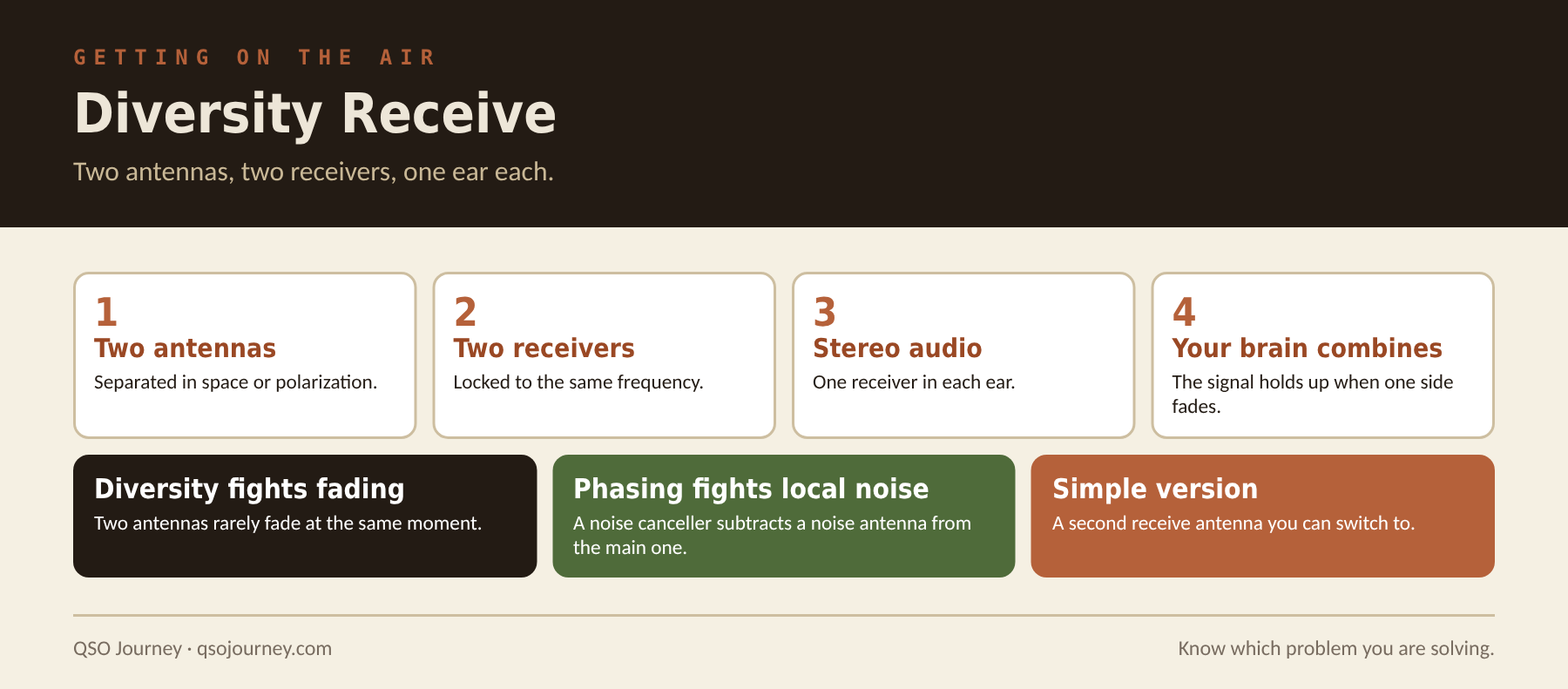
Signals that arrive by ionospheric propagation fade constantly, and two antennas separated by a few wavelengths, or with different polarizations, rarely fade at the same moment. A diversity setup feeds each antenna to its own receiver, both locked to the same frequency, with one receiver in each ear through stereo headphones. Your brain combines the two, so when the signal drops out in one ear it’s often still readable in the other. Diversity fights fading. Local noise is a different problem, and the usual tool for that is a phasing noise canceller, which subtracts what a dedicated noise antenna hears from your main antenna.
The full version takes two separate antennas with real physical or polarization separation, two receivers locked together (such as the dual receivers in an Icom IC-7610, which has a dedicated diversity mode), and stereo headphones. That’s why it stays mostly a serious DXer and contester technique.
You can get some of the benefit without a dual-receiver rig. A second receive antenna, positioned or oriented differently, that you can switch to when a signal is buried lets you compare what two antennas hear and pick the cleaner copy. If you chase weak DX and your noise floor is the limit, even a simple low-noise loop or Beverage-style wire for comparison is worth having.
Antenna Modeling Software: EZNEC and 4nec2
Before you cut a single piece of wire, modeling software can tell you almost exactly how a design will perform: gain, pattern, feed impedance, all of it. EZNEC and 4nec2 are the two names that come up constantly, and both run on the same engine.
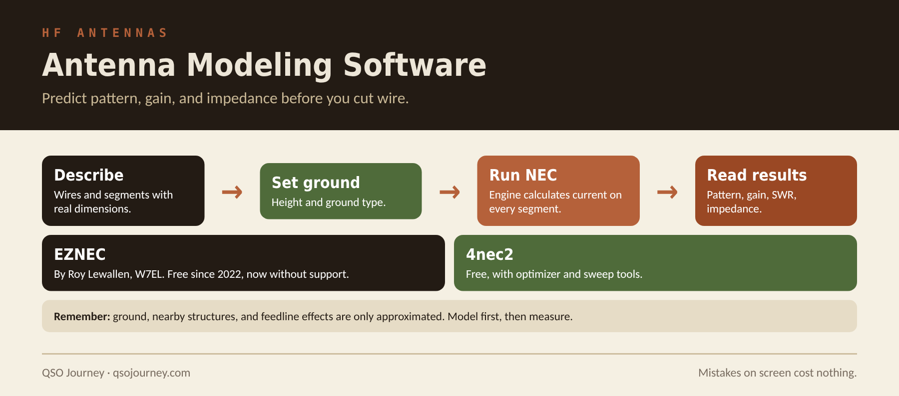
Both are front ends for NEC (Numerical Electromagnetics Code), a modeling engine originally developed at Lawrence Livermore National Laboratory. You describe the antenna as connected wire segments with real dimensions, and NEC calculates how current distributes across it and predicts the pattern, gain and impedance.
EZNEC, written by Roy Lewallen, W7EL, was for years the commercial standard for amateur antenna design, with a cleaner interface and better documentation. When Lewallen retired at the start of 2022 he made EZNEC free, though it no longer gets support or updates. 4nec2 is also free, covers most of the same ground and adds optimizer and sweep tools. Either one will give you a usable prediction of how a dipole, vertical or beam will perform at your height over your ground.
Modeling won’t replace real-world testing, since ground conductivity and nearby structures are only approximated. But it catches design mistakes before they cost you an afternoon and a pile of wire, and it lets you compare tradeoffs (height versus gain, element spacing, loop shape) on screen first. If you’re designing anything beyond a basic dipole, an hour in 4nec2 is time well spent.
- Start with a simple dipole you can check against known results.
- Use enough segments. Too few per wire gives unreliable results, especially near feed points and bends.
- Model real ground. Perfect ground and real average ground can differ a lot, especially for low antennas and verticals.
- Include nearby conductors that matter, such as a tower, mast or another antenna close by.
- Treat feed point impedance as a starting point and confirm it with an analyzer once built.
Both programs can sweep a frequency range and plot SWR across a band, and comparing two design choices side by side is often more useful than chasing exact numbers for one. My Antenna Calculators handle the quick math for Moxons, Yagis and J-poles.
Related reading: What Is a Moxon Antenna? · Antenna Height · Remote SDR Listening