

Part of our Icom IC-7300 Mark II: The Complete Guide.
A radio that behaves perfectly on the bench can turn noisy, unstable, or frustrating once it’s part of a real shack with an antenna, a power supply, a computer, and a network cable all nearby. This covers everything around the Mark II that decides how well it actually performs: the built-in tuner and when to go external, the separate RX antenna ports, power, and grounding and RFI.
- Getting the most from the built-in tuner
- When to add an external tuner
- The separate RX antenna ports
- Power supply considerations
- Grounding and RFI prevention
Getting the most from the built-in tuner
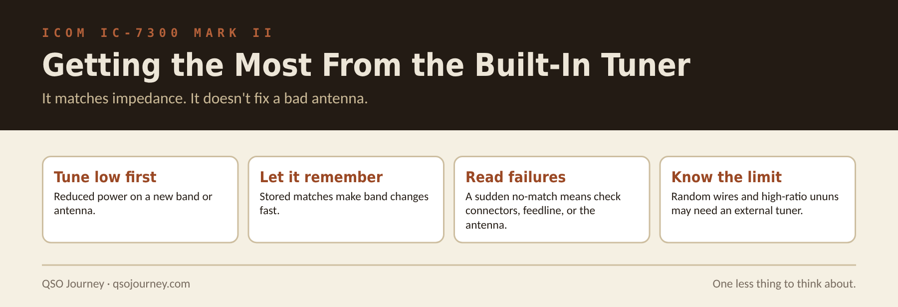
The built-in automatic tuner is one of the reasons the IC-7300 line is such a good base radio choice: no separate box, no extra cable. Like any automatic tuner, though, it matches impedance. It doesn’t make a bad antenna radiate better. If your SWR is high because of a real antenna or feedline problem, the tuner might let you transmit without the radio folding back power, but you’re still not getting your signal out efficiently. Use it for reasonable mismatches, not as a bandage for a broken antenna system.
Tune at reduced power on a new band or antenna before running full output. Once it finds a match it stores that memory and recalls it quickly on future band changes, which is the real time saver once you’ve built up regular use across your usual bands.
If the tuner suddenly can’t find a match on a band it usually handles fine, treat that as information, not just an inconvenience. It usually means something changed physically, a connector working loose, a feedline issue, or antenna damage. Check that before assuming the tuner itself is at fault.
- Tune at low power on any new band or antenna before running full output.
- Let it store memories for your regular antennas rather than retuning from scratch every session.
- Investigate rather than fight a tuner that suddenly can’t find a match it used to handle easily.
- Know its matching range limits and use an external tuner for genuinely non-resonant setups.
When to add an external tuner
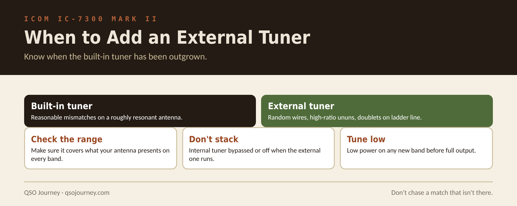
The internal tuner is designed for reasonable mismatches on a roughly resonant antenna, not a random-length wire with a high-ratio unun that presents wildly varying impedance across bands. Run something well outside a normal resonant antenna’s behavior and the internal tuner may refuse to find a match, or find one that’s technically within range but not efficient.
This comes up with random wire antennas, multiband doublets fed with ladder line, or any antenna system built around flexibility rather than resonance on every band. An external automatic or manual tuner with a wider matching range picks up where the internal one leaves off. Wire it in between the radio’s antenna port and your feedline, and put the internal tuner in bypass while the external unit handles the match. Running both in the circuit at once just adds complexity without benefit.
- Confirm the external tuner’s matching range covers what your antenna presents across bands.
- Bypass the internal tuner when running an external one. Don’t stack both.
- Tune at low power on any new band before running full output, same as with the internal tuner.
If your antenna is resonant or close to it on the bands you use, the internal tuner is probably all you need. If you’re building a random wire, my random wire antenna guide covers the lengths that make any tuner’s job easier.
The separate RX antenna ports
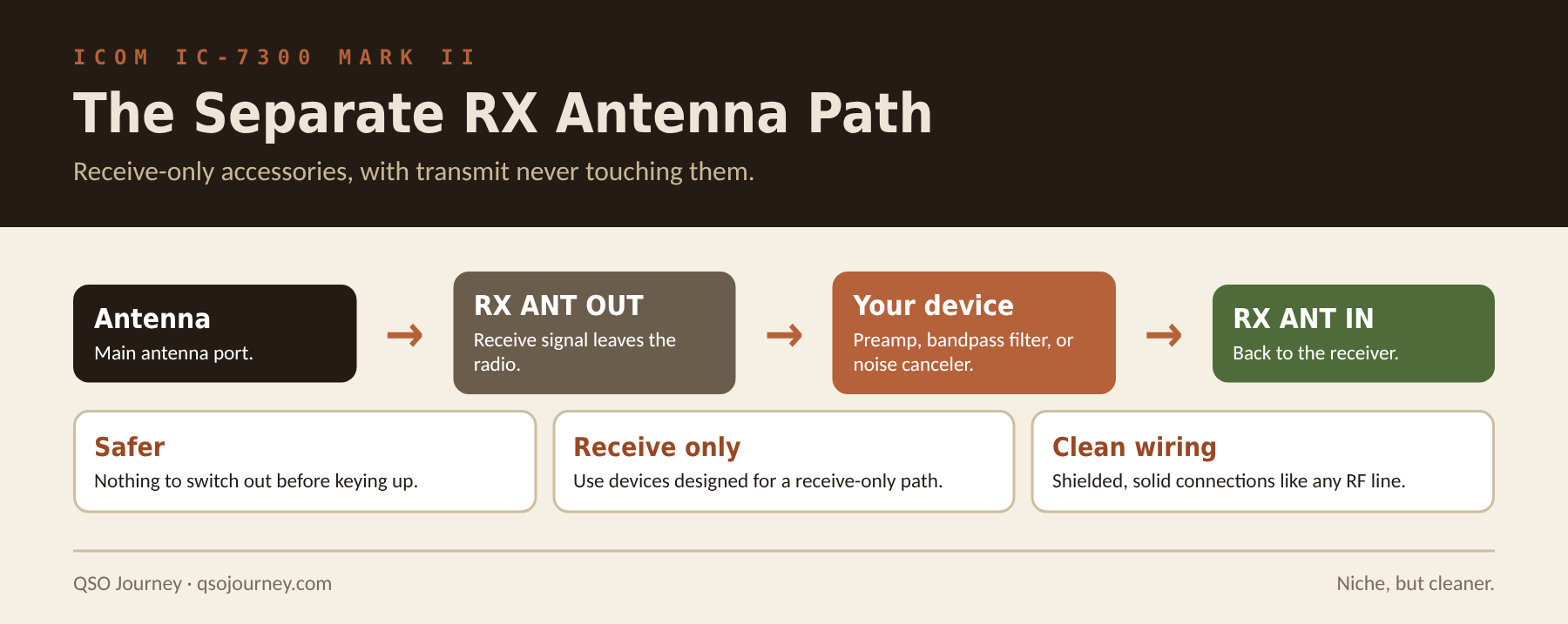
The Mark II added dedicated RX antenna in and out connectors, separate from the main transmit antenna port. Rather than splitting your main antenna line to insert a receive-only accessory, the receive signal leaves the radio through RX ANT OUT, passes through whatever external device you’ve connected, and comes back in through RX ANT IN, all without touching the transmit path.
That path is for a receive preamp for weak-signal work on a quiet band, a bandpass filter to knock down strong out-of-band signals, or a noise-canceling device that needs a dedicated receive antenna to compare against. On radios without a separate receive path, adding a preamp or filter usually meant a relay or manual switch to take it out of the circuit before transmitting, since most such devices can’t handle transmit power. The Mark II removes that failure point. There’s nothing to forget to switch out before keying up.
- Confirm your accessory is designed for a receive-only signal path, not general antenna switching.
- Keep the wiring between RX ANT IN and OUT clean and properly shielded, like any other RF connection.
- Test with the main transmit antenna disconnected first to confirm the receive path alone works as expected.
Power supply considerations
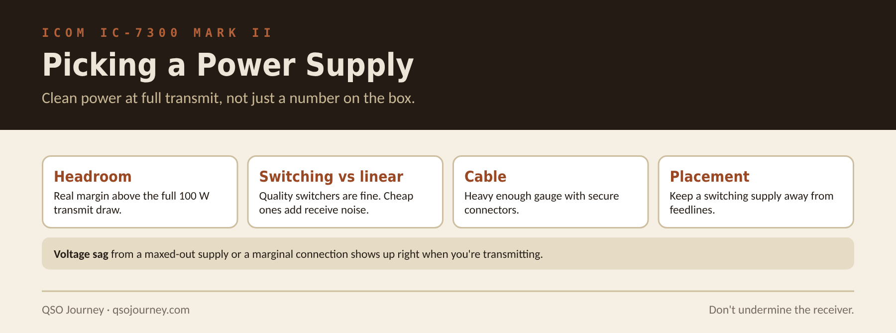
The Mark II’s lower standby draw is a nice improvement, but full transmit current still demands a real power supply. Check the radio’s actual transmit current draw at full 100W output and pick a supply with real headroom above it, not one barely rated for peak draw. A supply running near its limit is more prone to voltage sag exactly when you need clean power most, mid-transmission.
A quality switching supply is generally fine and more compact, but cheap switching supplies are a common source of broadband noise on receive. If a noise floor shows up after adding a new supply, that’s the first thing to suspect. A linear supply avoids the concern entirely at the cost of size and weight. Use appropriately heavy gauge power cable and secure connectors too. A marginal connection under load causes the same sag as an underpowered supply. For sizing batteries and solar if you run off-grid, my power calculator does the math.
- Confirm real current headroom above the radio’s full transmit draw.
- Listen for new receive noise after adding any switching supply, and address it early.
- Use properly sized cable and secure connectors between supply and radio.
- Keep a switching supply away from antenna feedlines to minimize noise coupling.
Grounding and RFI prevention
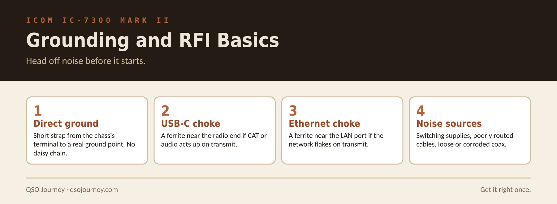
Run a short, direct ground strap from the radio’s chassis ground terminal to a proper station ground point, not through a daisy chain of other equipment. A shared or indirect ground path is a common way for RF to get into places it shouldn’t, like your computer’s USB devices or audio interface.
Since the Mark II’s CAT, audio, and PTT all ride the same USB-C cable, a poorly grounded station can introduce RF into that connection. It shows up as erratic CAT behavior or audio artifacts specifically during transmit. A ferrite choke on the USB-C cable near the radio end is a cheap first step. The same goes for the Ethernet cable if you run the LAN port for RS-BA1: add a choke near the radio’s Ethernet port if network flakiness lines up with transmitting.
Common noise sources worth checking
- A shared or daisy-chained ground rather than a direct run to a proper ground point.
- Unshielded or poorly routed USB-C and Ethernet cables near the radio.
- Nearby switching power supplies, a frequent source of broadband noise on receive.
- Loose or corroded coax connectors, which can both radiate and pick up noise.
None of this is complicated, but it prevents a lot of confusing, intermittent problems down the line. Get the ground, power, and cable routing right once, and the radio’s receiver gets to shine instead of fighting your own station’s noise. If something still isn’t right, see common IC-7300 Mark II problems.