

Part of our Building Your First Ham Radio Station guide.
A mobile radio with a roof-mounted antenna is one of the biggest range upgrades you can make over a handheld, and a sloppy install is one of the most common sources of mystery problems. This guide covers picking the radio, installing it properly, and chasing down the noise that shows up afterward. My Jeep runs an AnyTone AT-D578UV III Plus for VHF and UHF and a Yaesu FT-891 with an ATAS-120A for HF, so I’ve worked through all of this firsthand. For HF-specific antennas and mounts, see Setting Up HF for Mobile Operating, and for GMRS, Installing a GMRS Mobile.
Jump to: Dual-band vs tri-band · Installing the radio · Alternator whine and vehicle noise
Choosing a Dual-Band vs Tri-Band Mobile Radio
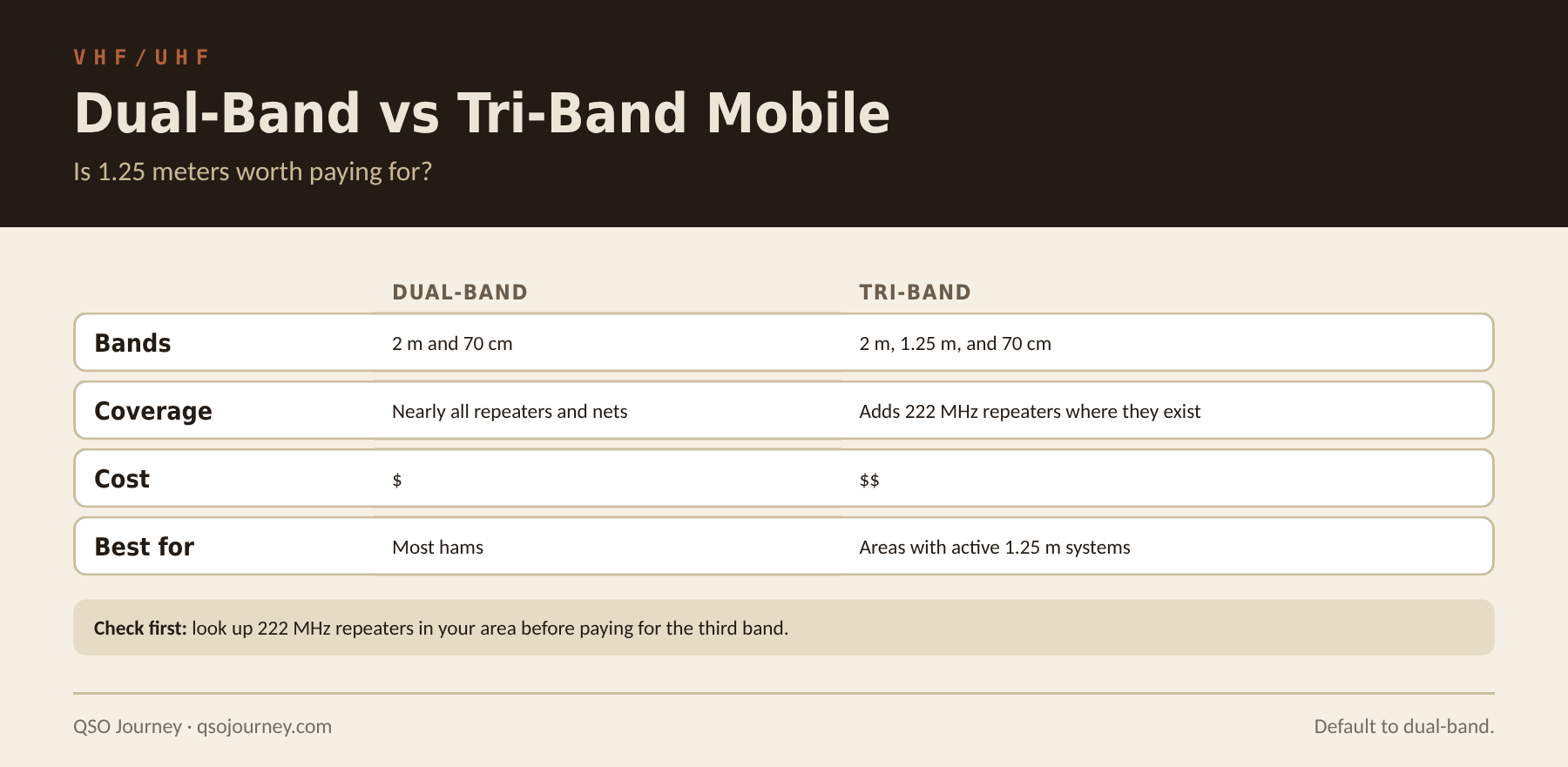
A dual-band mobile covers 2 meters and 70 centimeters, the two most active VHF and UHF bands in the US by a wide margin. Nearly every repeater system, most local nets and most simplex activity live there, so a dual-band covers the large majority of hams without compromise.
A tri-band adds 1.25 meters (222 MHz). It’s a useful band where it has active repeaters, since it’s far less crowded, but activity is regionally spotty: some areas have strong 222 networks and others have essentially nothing. A tri-band adds no value if there’s nothing to use the third band for, so check your area first (more in Why the 1.25 Meter Band Is Worth a Look).
- Default to dual-band unless you have a specific, confirmed reason for the third band. The money saved is better spent on a better antenna.
- Curious about 222 without replacing your mobile? Try a tri-band handheld first, add a single-band 222 mobile alongside, or ask a local club who’s active on the band.
- A tri-band radio needs a tri-band antenna. A 2m/70cm antenna won’t necessarily match well on 222.
Installing a Dual-Band Mobile in Your Vehicle
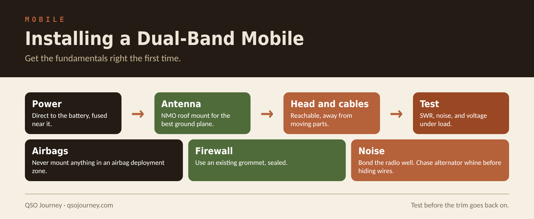
- Power straight to the battery. Don’t tap an accessory circuit. Size the wire for the radio’s current and the run length, and fuse both the positive and negative leads close to the battery, not just at the radio. I cover the gauge chart and fusing rules in 12V DC Power for Ham Radio.
- Mount the antenna for ground plane. An NMO mount through the roof gives the best ground plane and performance. Trunk lip and hatch mounts avoid drilling, but less metal around the antenna base usually means worse SWR and efficiency.
- Plan the control head before running cable. On radios with a separable head, pick a spot you can comfortably see and reach first. (The 578 doesn’t have a detachable head, so I use its BT-01 Bluetooth controller instead.) Route control and power cables away from factory harnesses and moving parts, and secure them so nothing rattles loose or gets pinched.
- Keep clear of airbags. Check the owner’s manual for deployment zones before mounting a head, mic hanger or bracket. Dashboards, A-pillars and seat sides often hide airbags, and anything in their path becomes a projectile in a crash. Use an existing firewall grommet where you can, and seal any hole you drill.
- Ground beyond the chassis. Chassis ground paths in modern vehicles aren’t always electrically clean. A dedicated strap from the radio chassis to the battery ground point often fixes noise that chassis grounding alone doesn’t.
- Test before you button it up. Check SWR on both bands, listen for engine and alternator noise with the vehicle running, and confirm the radio holds steady voltage under transmit. Catching a problem now is far easier than after everything is hidden behind trim panels.
Diagnosing Alternator Whine and Vehicle Electrical Noise
If you’ve run HF mobile, you know the sound: a whine that rises and falls with engine RPM, right on top of weak signals. It’s one of the most common noise problems in mobile installs, and it shows up on VHF and UHF too.

Alternators put ripple on the DC output as they switch between diode pairs, and the ripple frequency scales with RPM, which is why the pitch tracks engine speed. It reaches the radio two ways: conducted through the power leads, or radiated and picked up by the antenna and feedline.
Find the path first
With the engine running, swap the antenna for a dummy load. If the whine disappears, it’s coming in through the antenna system. If it stays, it’s riding in on the power leads. Running the radio briefly from a separate battery is another check: if the whine vanishes, the vehicle wiring is the path.
- Conducted noise is usually the bigger contributor, so start here. Run the power leads directly to the battery terminals, keep them short, and add a quality DC noise filter or ferrite chokes near both ends of the run. Cheap thin aftermarket leads make it worse.
- Radiated noise: if filtering the power doesn’t clear it, check that the antenna mount has a solid ground to the body, add a common-mode choke on the feedline near the radio, and route coax away from the engine bay and alternator wiring. In stubborn cases, a braided ground strap between the engine block and the chassis reduces noise at the source.
Related reading: Mobile Antenna Mounts, Grounding, and Noise · My ATAS-120A Review · Diagnosing and Killing HF Noise