

Part of our Building Your First Ham Radio Station guide.
Most mystery problems in a 12 volt station come down to power: a radio that resets on transmit, output below spec, an intermittent connection in a go-kit, or worse, melted wire. Doing it right isn’t expensive or complicated. It comes down to four things: a standard connector, good crimps, fuses that protect the wire, and wire thick enough for the current. I wire my shack, my DIY 100Ah LiFePO4 battery box and my go-boxes this way.
Jump to: Why Powerpoles · Crimping them right · Fusing · Wire gauge
Anderson Powerpoles: Why Hams Standardize on Them
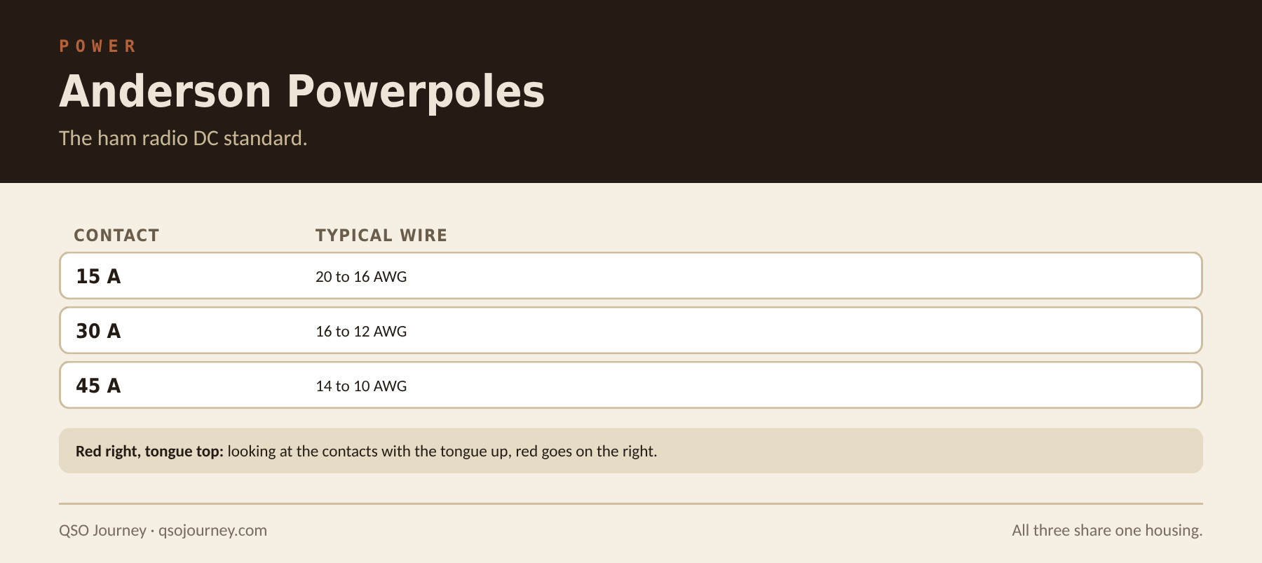
Powerpoles are genderless: any connector mates with any other, whatever equipment it came from. They snap together and pull apart cleanly, carry serious current for their size, and lock into a keyed housing that prevents reverse polarity when assembled correctly. ARES and RACES groups adopted them decades ago because interoperability matters in an emergency. If every radio in the room uses the same connector, anyone’s power supply can run anyone’s radio.
Most radios ship with a proprietary or generic connector that only works with their own supply. Put Powerpoles on everything, radios, power supply, battery packs and solar, and any power source can run any radio with no adapter hunt. The standard orientation is red right, tongue top: looking at the contact end with the metal tongue on top, red is on the right and black on the left. Following that standard, not just whatever works for your own gear, is what makes your connectors work with everyone else’s.
| Contact | Typical wire |
|---|---|
| 15 A | 20 to 16 AWG |
| 30 A | 16 to 12 AWG |
| 45 A | 14 to 10 AWG |
All three contacts fit the same housing, so a 15 A and a 45 A connector still mate. Pick the contact by the wire gauge you’re crimping. An assortment kit and a proper crimper pay for themselves the first time you borrow power at Field Day or a POTA activation.
Crimping Powerpoles the Right Way

A bad crimp is one of the most common causes of intermittent power problems, and the fix is almost always technique, not the connector.
- Use a real crimper. Pliers or a generic crimper will close the terminal but won’t give the geometry it needs. A dedicated Powerpole crimper, or a ratcheting crimper with the right die, is worth the modest cost.
- Match the contact to the wire. A contact sized for much thicker or thinner wire gives a weak connection even with perfect technique.
- Strip to the right length. Enough to seat the wire fully in the barrel, with no bare wire past the edge and no insulation caught inside.
- Test it. Give the wire a firm tug; it shouldn’t move. Look for a uniform crimp with no gaps. Before trusting a batch in the field, test it under real load, since a crimp can look fine and still have resistance.
- Assemble red right, tongue top. Push each contact into the housing until it clicks.
Fusing Your 12V Station

- The fuse protects the wire, not the radio. Put it as close to the battery or power supply as practical. A fuse only at the radio end does nothing for a short anywhere along the run before it.
- Size the fuse to the wire. Rate it at or below the wire’s safe current capacity, so the fuse blows before the wire overheats, regardless of what the radio’s spec sheet says.
- Use a fused distribution block. One heavy fused feed from the battery to a central block, then a separately fused branch to each radio and accessory. Daisy-chaining several devices off one big fuse defeats individual protection.
- In a vehicle, fuse both leads at the battery. Run positive and negative directly to the battery and fuse both near it, which is what most manufacturers specify. Fusing the negative protects the radio’s cable if the engine ground strap fails and current tries to return through it.
Common mistakes: fusing only at the radio, using a fuse rated above what the wire can handle, skipping the fuse on a “short” run (short runs still short circuit), and reusing a mystery fuse from a parts bin.
Choosing Wire Gauge for DC Power Runs
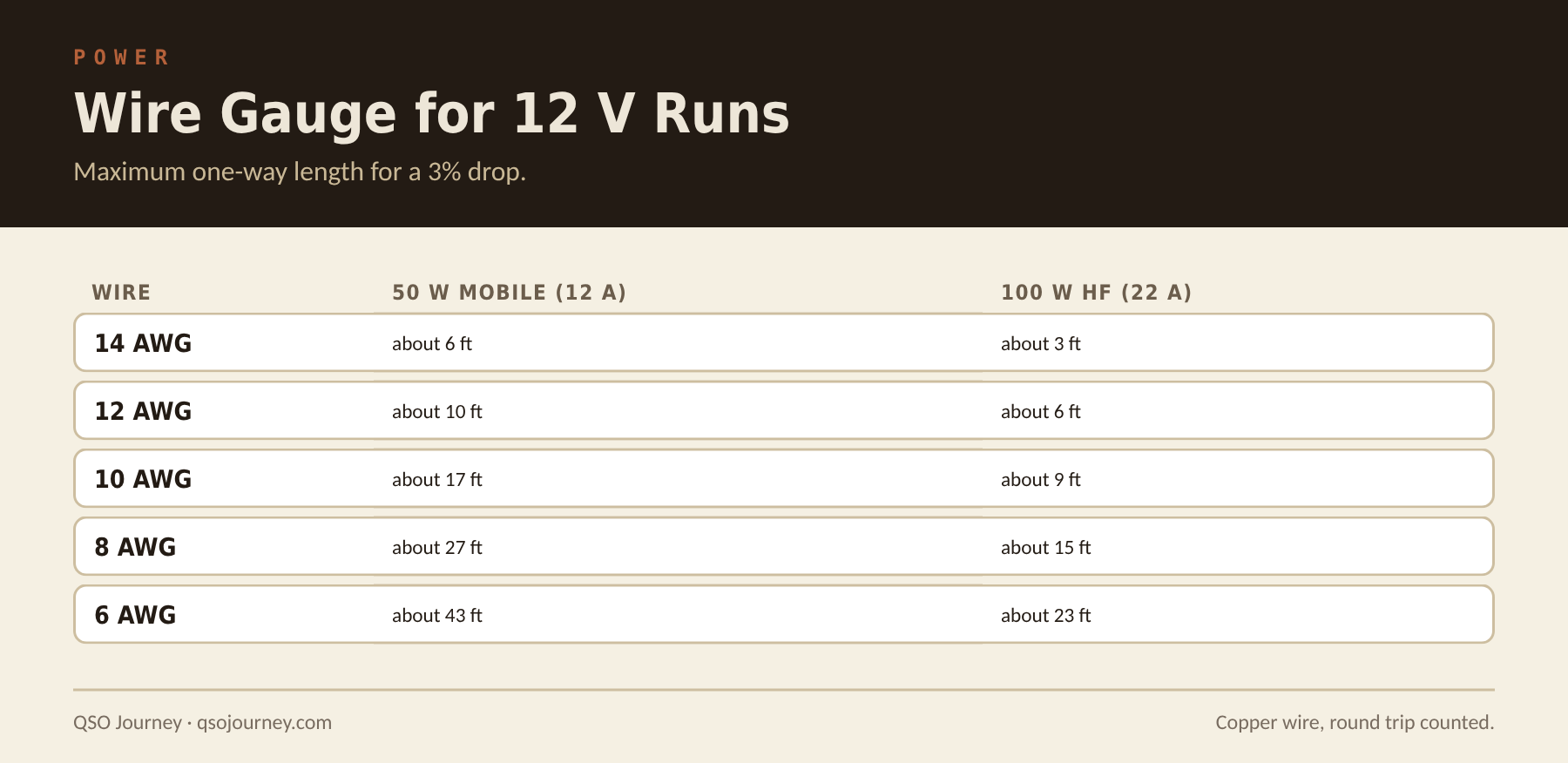
At 12 volts, a small voltage drop is a big percentage loss. A radio that wants 13.8 V but sees 11.5 V on transmit underperforms, and in worse cases its low-voltage protection shuts it down. Two numbers decide the gauge: the radio’s current at full transmit power (not its average) and the length of the run.
| Wire | 50 W mobile (about 12 A) | 100 W HF (about 22 A) |
|---|---|---|
| 14 AWG | about 6 ft | about 3 ft |
| 12 AWG | about 10 ft | about 6 ft |
| 10 AWG | about 17 ft | about 9 ft |
| 8 AWG | about 27 ft | about 15 ft |
| 6 AWG | about 43 ft | about 23 ft |
These are approximate maximum one-way distances for about a 3 percent drop at 13.8 volts, copper wire, counting both conductors. Treat them as a starting point and size up if you’re close. Thicker wire costs a little more and never causes a problem. Undersized wire is a problem you’ll chase for as long as you use that run. Signs of undersized wire: output below spec, resets or low-voltage warnings on transmit, or noticeably lower voltage at the radio than at the source under load. Check loose connections and a weak supply at the same time. My Power Calculator does the voltage-drop math for your exact run.
For keeping it all running in an outage, see backup power for the shack, and for a vehicle, Installing a Ham Dual-Band Mobile Radio in Your Vehicle.