

Part of our Building Your First Ham Radio Station guide.
Almost everyone wants one antenna that covers several HF bands. There are four classic ways to get there: a non-resonant wire fed with ladder line or an off-center feed (the G5RV and Windom), several resonant dipoles on one feed point (the fan dipole), traps that electrically shorten an element on the higher bands, and loading coils that make a short antenna act longer. Every one of them works, and every one of them trades something away. Here is how each works, what it costs you, and when I’d pick it. If you just want the simplest multiband wire in 2026, my answer is still usually an EFHW, and I compare that one in EFHW vs Random Wire.
Jump to: G5RV and Windom · Fan dipoles · Trap dipoles and verticals · Loading coils and shortened verticals
The G5RV and Windom: Are They Still Worth It?
The G5RV and Windom show up constantly in older antenna books and forum threads, and newer hams often wonder if they’re still worth building now that EFHWs and modern multiband verticals exist. Both designs work, but both come from an era with different assumptions about what gear you had on hand.
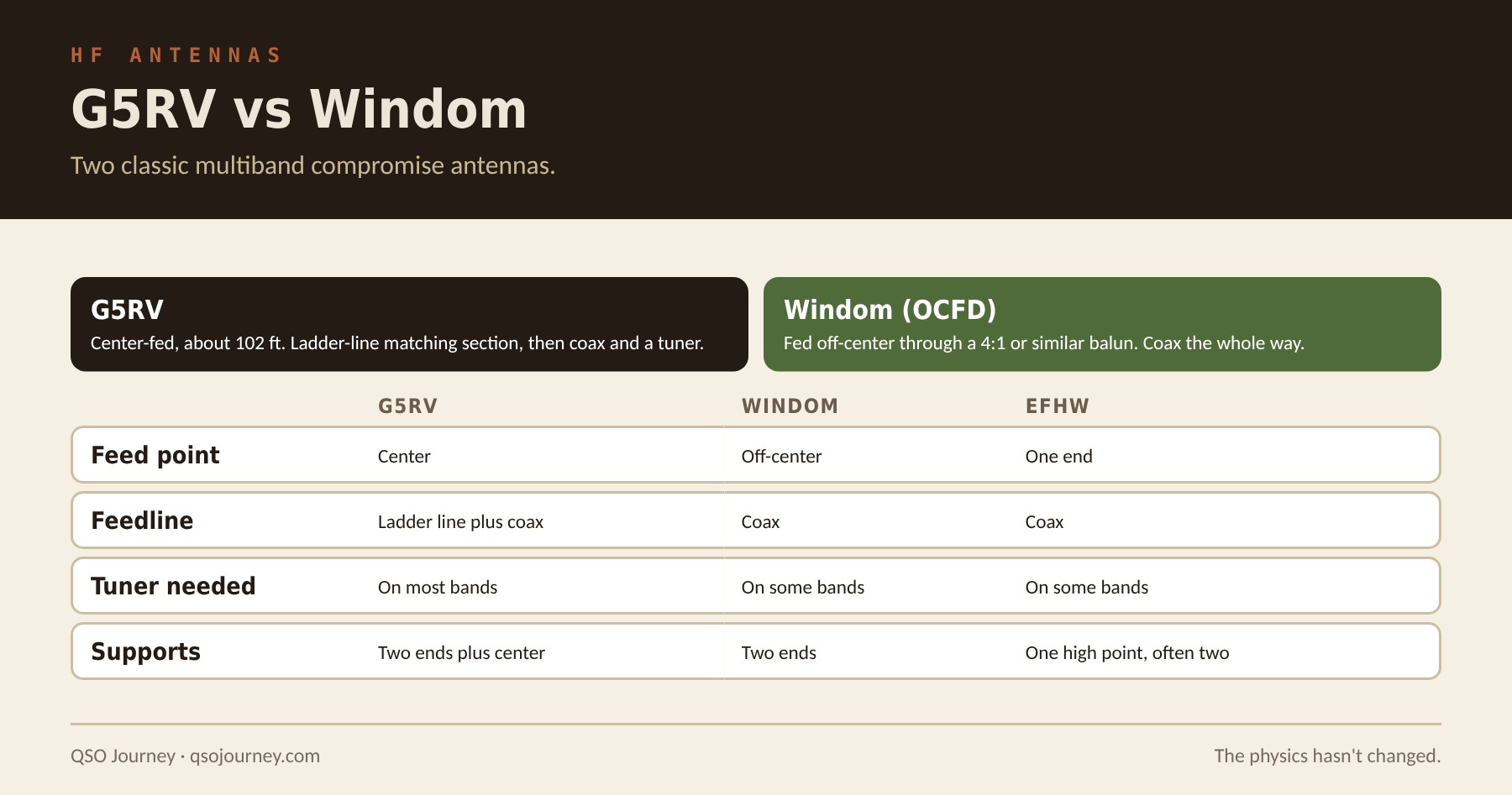
How the G5RV actually works
The G5RV, designed by Louis Varney, G5RV, in the 1940s and widely publicized in the late 1950s, is a center-fed dipole of a specific length (typically 102 feet for the full-size version) connected to a section of open-wire ladder line. That section transforms the wildly varying feed impedance across multiple bands into something a tuner can handle. It’s a true multiband compromise: the antenna isn’t resonant on most of the bands it covers, and it relies entirely on your tuner and the ladder line section to make each band usable.
The Windom’s off-center feed
The Windom takes a different approach. Feeding a horizontal dipole off-center instead of at the middle produces a usable impedance on several harmonically related bands without the ladder line section the G5RV depends on. Modern Windom variants, usually called off-center-fed dipoles or OCFDs, use a 4:1 or 6:1 balun at the feed point and coax the rest of the way, which is simpler to deploy than the G5RV’s twin-lead. I go deeper on that design in Off-Center-Fed Dipoles.
Do they still make sense today?
Both antennas work exactly as well as they did decades ago, since the physics hasn’t changed. What has changed is the alternatives. A modern EFHW with a good 49:1 transformer covers similar multiband territory with a single wire, a single support and no ladder line to manage. I’d only reach for a G5RV or Windom today if you specifically want the classic design, already have the ladder line and the space for it, or like the history behind them.
| Antenna | Typical size | Feed |
|---|---|---|
| Full-size G5RV | 102 ft flat top | About 34 ft of open-wire line (shorter with 450 ohm window line), then coax |
| Half-size G5RV | 51 ft flat top | Shorter matching section, for 20 m and up |
| Windom (OCFD) for 80 m | About 133 ft | Fed roughly one third of the way from one end |
| Windom (OCFD) for 40 m | About 67 ft | Same off-center ratio |
Exact matching section lengths depend on the ladder line’s velocity factor, so follow the plans for the line you actually have. Whichever design you build, put a common-mode choke where the coax starts, since both designs are prone to RF on the outside of the feedline. My 1:1 common-mode choke build handles that.
Fan Dipoles: One Feedline, Multiple Bands
A fan dipole solves the multiband problem with an almost embarrassingly simple approach. Instead of one antenna trying to cover several bands through traps or compromise, you hang several resonant dipoles off the same feed point.
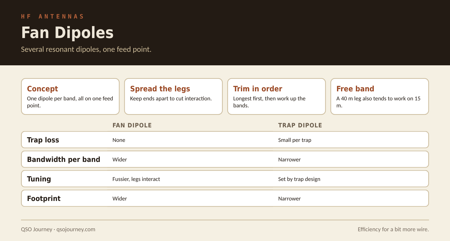
The concept
A fan dipole is several individually cut, resonant half-wave dipoles, each for a different band, all connected to the same feed point and center support and fanned out at slightly different angles so the wires don’t touch. Because each leg is resonant on its own band, there’s no trap loss and no compromise tuning. Each dipole does its job on its own frequency while presenting a high enough impedance on the other bands to stay mostly out of the way.
Where it gets tricky
The wires interact more than the simple description suggests, especially between bands like 40 and 20 meters where harmonic relationships cause more coupling. Getting a clean SWR on every band usually takes some trimming and iteration, because adjusting one leg can shift the resonance of another. Keeping the legs physically separated at the ends, by spreading them at different angles or using separate support points, matters more than it looks like it should on paper.
Fan dipole vs trap dipole
Compared to a trap dipole, a fan dipole avoids trap loss entirely and tends to have better bandwidth on each band, since every leg is truly resonant rather than electrically shortened. The tradeoff is more wire, more end supports (or a wider spread at one support), and fussier trimming. For a permanent multiband install where you have room for the wider profile, I’d generally choose a fan dipole over a trap dipole for the efficiency alone.
Building tips
- Cut each leg using 468 divided by the frequency in MHz for total dipole length in feet, then add a little extra for trimming.
- Hang the longest dipole first and trim it before adding the shorter ones. Adding legs shifts the resonance of the ones already there.
- Spread the leg ends as far apart as practical, using separate ropes or spreaders.
- A 40 meter leg also resonates near 15 meters at its third harmonic, so you may not need a separate 15 meter leg.
- Put a 1:1 choke balun at the feed point to keep RF off the coax.
An antenna analyzer makes trimming far faster, since you can see each band’s resonance at once instead of checking SWR band by band on the radio. I use a NanoVNA and a RigExpert Stick Pro.
Trap Dipoles and Verticals: How They Work and Where They Fall Short
Trap antennas promise something appealing: one antenna, multiple bands, no tuner required. That promise is real, but it comes with tradeoffs that don’t always make it into the sales copy.
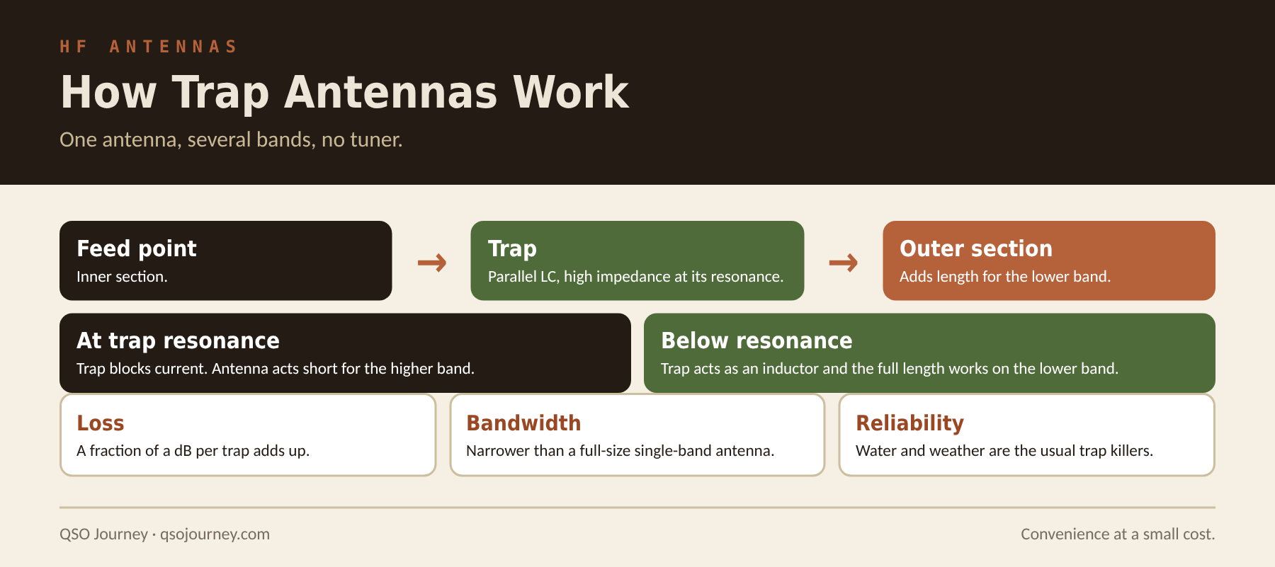
How a trap actually works
A trap is a parallel LC circuit, an inductor and capacitor wired together, inserted into the antenna element at a calculated point. At its resonant frequency the trap presents a very high impedance and acts like an insulator, electrically shortening the antenna to the right length for that band. At other frequencies it looks more like a simple inductor and lets current through to the rest of the element for the lower bands. Stack several traps along a dipole or vertical and you get an antenna that’s resonant on several bands without ever touching a tuner.
The real tradeoffs
Traps aren’t free. Each one adds loss, typically a fraction of a dB, and that adds up across a multi-trap design. Traps are also a common failure point: they’re exposed to weather, they detune if water gets in, and they’re mechanically more fragile than plain wire. Trap antennas also tend to have narrower usable bandwidth on each band than a full-size single-band antenna, since the traps are tuned for a specific frequency.
When a trap antenna makes sense
Trap verticals and dipoles shine when you want true no-tuner multiband operation from one relatively compact antenna, especially verticals, where a trap design can be dramatically shorter than a full-size antenna for its lowest band. If you’re comfortable trading a bit of efficiency and long-term reliability for convenience and a smaller footprint, a quality trap antenna from a reputable manufacturer is a reasonable choice. I’d still lean toward an EFHW or a tuned wire if simplicity and low maintenance matter more to you than tuner-free operation.
Keeping trap antennas working
- Inspect traps every season for cracked covers, corrosion and water intrusion.
- Check SWR across each band at least once a year. A drift on one band often points to a specific trap.
- Don’t exceed the power rating. Traps carry high voltage and current, and overheating can permanently detune them.
- If you build your own, use weatherproof construction and measure each trap’s resonant frequency before installing it.
A trap that has absorbed water usually shows up as a band that suddenly won’t tune, or a resonance that wanders with the weather. Replacing a single trap is often cheaper and faster than replacing the whole antenna.
Loading Coils and Shortened Verticals
Screwdriver antennas, mobile whips and compact verticals all lean on the same trick to fit a low-band antenna into a fraction of its natural length: a loading coil. Understanding what that coil is doing explains why some shortened antennas perform noticeably better than others of similar size.
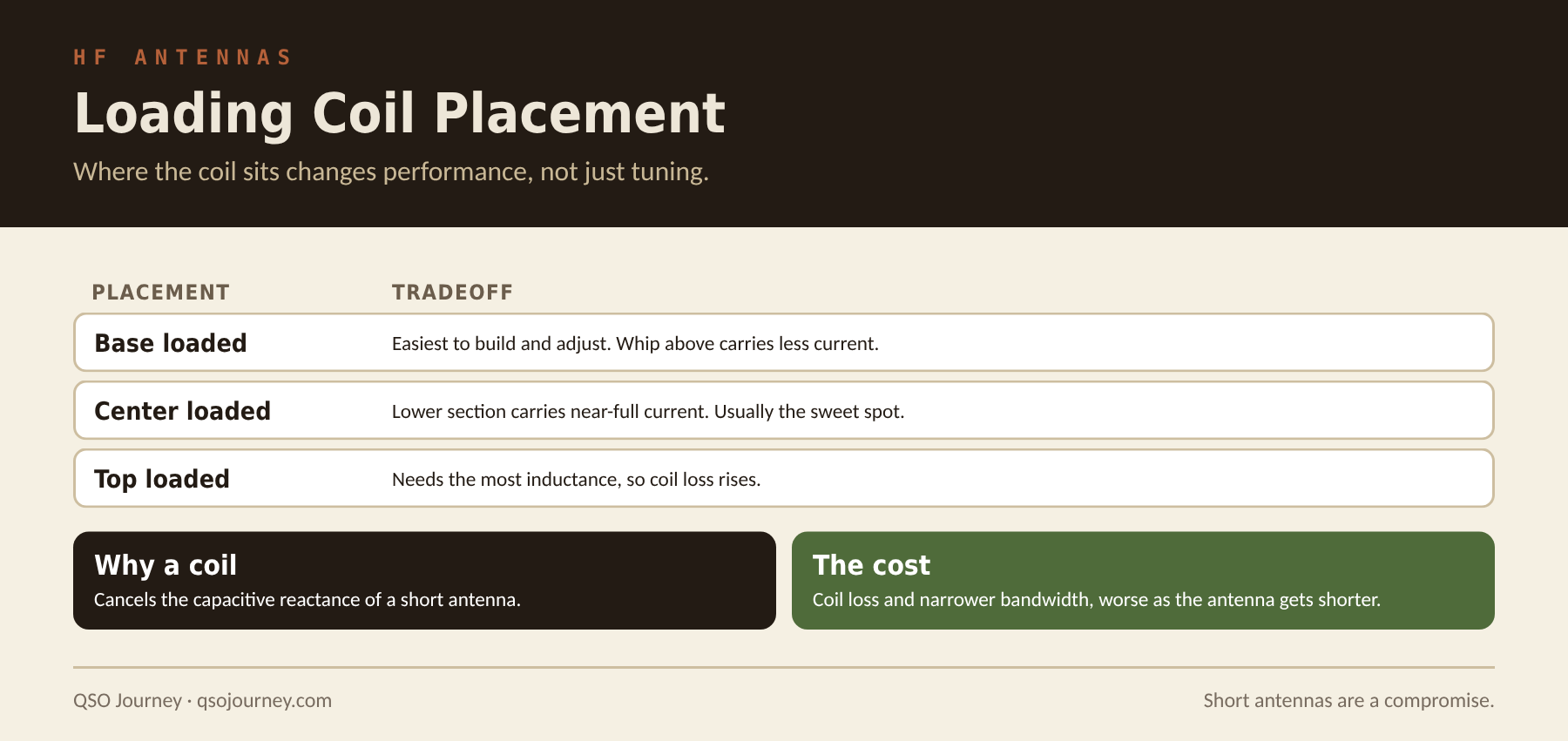
Why a short antenna needs help
A quarter-wave vertical on 40 meters wants to be roughly 33 feet tall. Shrink it to something practical and the feed point impedance becomes strongly capacitive, so it no longer presents a resistance a transmitter or simple tuner can drive efficiently. A loading coil, an inductor inserted into the element, cancels that capacitive reactance, so from the transmitter’s point of view the short antenna behaves much more like a full-size resonant one.
Where you put the coil matters
Coil placement changes performance, not just tuning. A coil near the base is easier to build and adjust, but the short whip above it carries current that tapers off quickly toward the tip, so it radiates relatively little. Move the coil up toward the center and the section below it carries nearly full current, which raises radiation resistance and generally improves efficiency for the same overall length. Go too high, though, and the coil needs so much inductance that its own losses eat the gain, which is why center loading is the usual sweet spot. That’s part of why a center-loaded mobile whip typically outperforms a base-loaded one of similar length.
The real cost: bandwidth and efficiency
Every loading coil adds resistive loss, and the more aggressively an antenna is shortened, the more loading it needs and the more efficiency you give up. Shortened verticals also have notably narrower usable bandwidth than full-size antennas. None of that means they aren’t worth using. They’re often the only practical option for mobile or space-limited stations, and going in with realistic expectations makes the results a lot less disappointing.
Making a short antenna work better
- Use the tallest radiator you practically can. Every extra foot reduces the loading needed and the coil loss.
- Add a capacity hat above the coil if the design allows. It adds top loading and reduces the inductance required.
- Choose a low-loss coil: heavy wire, good spacing and a low-loss form.
- Give the antenna a good ground system or counterpoise. Ground loss is often bigger than coil loss on short verticals. See How Ground Radials Impact Your Vertical Antenna.
- Expect to retune when changing frequency, especially on the lower bands where bandwidth is very narrow.
Screwdriver antennas handle that last point by moving the coil tap with a motor, which is why they’re popular for mobile HF despite the efficiency tradeoffs. My Jeep runs a Yaesu ATAS-120A on the FT-891, and I wrote up how that goes in my ATAS-120A review.
Related reading: Full-Size Wire Loop Antennas · How to Build a Wire Dipole for HF on a Budget · Antenna Design Choices: Feed Point, Height and Vertical Mounting