

Part of our Building Your First Ham Radio Station guide.
I spent an evening going through the Falcon II AN/PRC-150(C) Application Guide, which is L3Harris’s catalog of everything that plugs into the PRC-150 manpack. I’m not here to talk about the radio. What caught my attention was the antenna section, because the military has the same problem we do in the field: get a usable HF signal out with gear that one person can carry, set up fast, and not break. Three antennas in that guide are worth a closer look for anyone doing portable or emergency HF. If you want the bigger picture of how the military picks its bands and gear, start with Antennas, Bands, and Radios the Military Actually Uses (and Why).
RF-1940: The Spooled Field Dipole
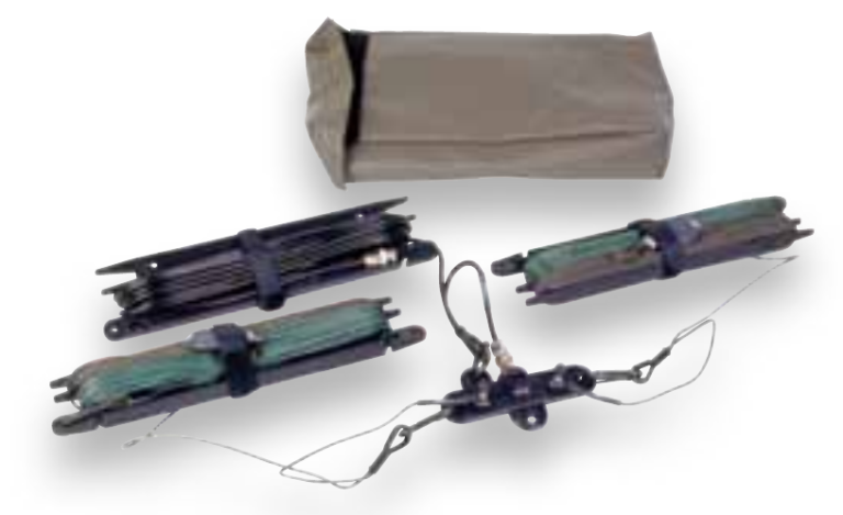
The RF-1940-AT001 is a portable dipole rated for 400 watts from 3 to 30 MHz. The clever part is the storage. Each leg lives on a flat spool that stays attached as part of the antenna. You unwind the wire to a marked frequency point and stop, and the leftover wire just stays on the spool. No cutting, no folding back, no guessing. Each spool also carries a throwing weight so you can get the ends up into trees, onto a building, or over a mast.
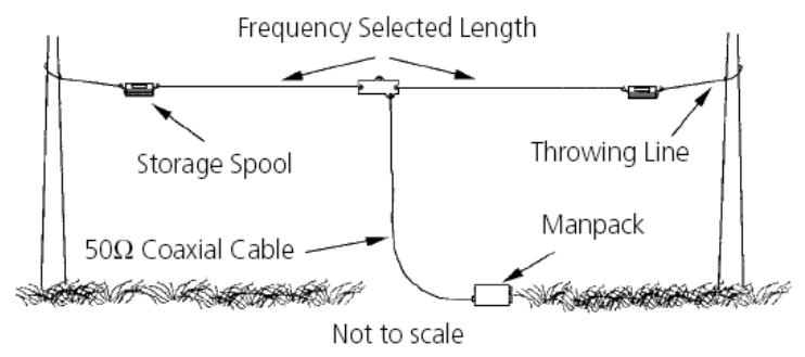
It can be rigged as a flat dipole, a sloping dipole, or a sloping vee. The guide’s range chart puts it mainly in the NVIS lane (0 to 500 km) when it’s up as a standard dipole, and stretches it into the 500 to 2,000 km range when it’s run as a sloper. That lines up with what we already know: low and flat throws energy up for regional coverage, and tilting it gives you some lower-angle radiation for distance. I cover how that height and angle play out in Antenna Height: How Much Does It Actually Matter.
- Frequency range: 3 to 30 MHz, 400 W max
- Deployed length: 150 ft (about 46 m)
- Packed size: 6 x 12 x 3 in, about 5 lb
- Includes: carry bag, 33 ft of RG-58 with BNC connectors, BNC to N adapter
The ham takeaway is the marked spool. Mark your own portable dipole legs for the bands you actually use and wind them on a flat winder. It’s cheap, and it makes setup in the dark a lot less painful. If you’re starting from scratch, How to Build a Wire Dipole Antenna for HF on a Budget walks through the build.
SB-V16B: The 16-Foot Vehicle Whip
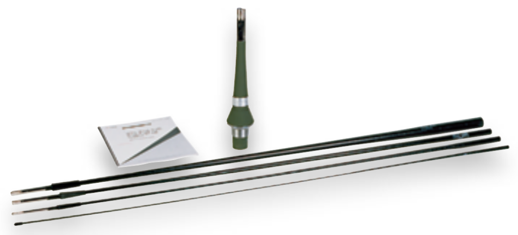
The SB-V16B is the classic military vehicle whip. It’s a self-supporting fiberglass antenna with the RF conductor embedded inside a woven fiberglass sheath, so it flexes instead of snapping when it meets a tree branch. Tapered 4-foot sections screw together to a full 16 feet, and it’s rated for 1 kW from 2 to 30 MHz. On a vehicle it bolts to the RF-292-01 Universal Antenna Mount through a 2-inch hole adapter plate.
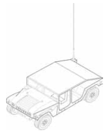
A 16-foot whip is nowhere near resonant across most of HF, so the tuner does the heavy lifting. The guide is honest about what it’s for: an omnidirectional, low-angle pattern for groundwave, with the range chart putting it at roughly 0 to 80 km standing straight up. That’s the weakness of any vertical whip. It puts very little energy straight up, which is exactly what you need for NVIS. The military’s fix, shown elsewhere in the same guide, is a tilt adapter that lays the whip back toward horizontal to get NVIS coverage on the move.
- Frequency range: 2 to 30 MHz, 1 kW max (coupler required)
- Height: 16 ft (about 4.8 m), about 5 lb
- Includes: feed-through base, tapered 4 ft sections, mounting hardware
If you run a vertical on your rig and wonder why regional nets are hard to hear, this is why. Tying the whip back or pairing it with a wire antenna at camp makes a real difference. For more on running a whip on your own vehicle, see Setting Up HF for Mobile Operating: Screwdriver Antennas and Grounding in a Vehicle and How to Tune a Vertical Whip Antenna for HF.
RF-1944-AT150: The No-Tuner Inverted Vee
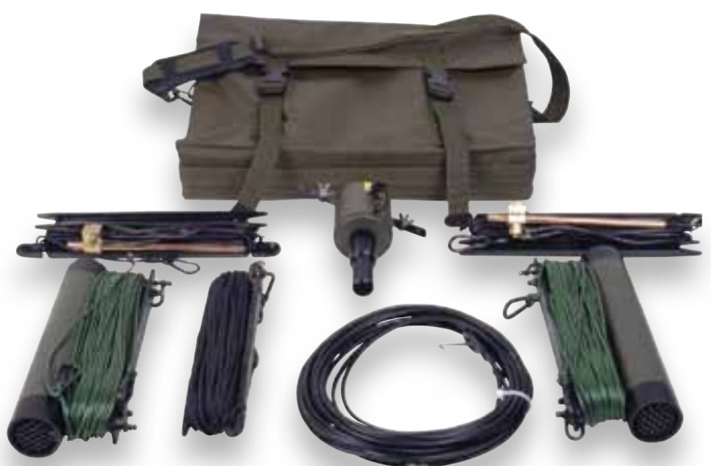
This is the one I find most interesting. The RF-1944-AT150 is a low-profile broadband dipole meant to be hung as an inverted vee. It covers 1.6 to 30 MHz at up to 150 watts, and it does it without an antenna coupler. The trick is termination resistors at the ends of each element. Terminating the dipole ends flattens the SWR across the entire range, so the radio can hop frequencies instantly (if SWR is new to you, What Is SWR, and Why Does It Actually Matter? covers it). That matters for ALE and frequency-agile waveforms, where waiting on a tuner every time the channel changes isn’t an option.
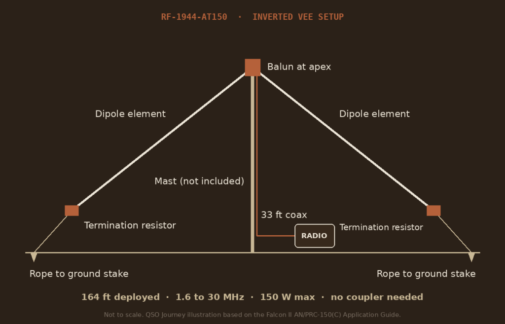
Setup is simple. Get the balun up on a mast with the halyard (the mast isn’t included), run the two elements down at an angle, and stake the ends. The guide lists it for NVIS, and the range chart shows the RF-1944 family reaching out toward 2,000 km.
- Frequency range: 1.6 to 30 MHz, 150 W max, no coupler needed
- Deployed length: 164 ft (about 50 m)
- Packed size: 12 x 20 x 3 in, 11 lb (14 lb for the RF-1944-AT151 version with a sledge hammer)
- Includes: balun, dipole elements, termination resistors, 33 ft coax, halyard, ground stakes, canvas bag
There’s no free lunch here. Those resistors turn some of your transmit power into heat, especially on the lower bands, so a terminated broadband antenna gives up efficiency compared to a resonant dipole. The military accepts that trade for speed and reliability. For hams, the same idea shows up in terminated folded dipole designs, and it’s worth considering if you want one wire that works on every band with no tuner in the loop.
What I Take Away From This
None of these antennas are magic. They’re well-built versions of designs hams already use: a spooled dipole, a big whip on a tuner, and a terminated inverted vee. What the military does well is match the antenna to the job. Whip for groundwave on the move, wire for NVIS at the halt, broadband when speed matters more than every last watt. That’s a good way to plan your own portable HF kit, too. If NVIS is the job, What Is an HF NVIS Regional Net? shows how it gets used, and Which Portable HF Antenna Should You Actually Bring? compares the options hams actually carry.